
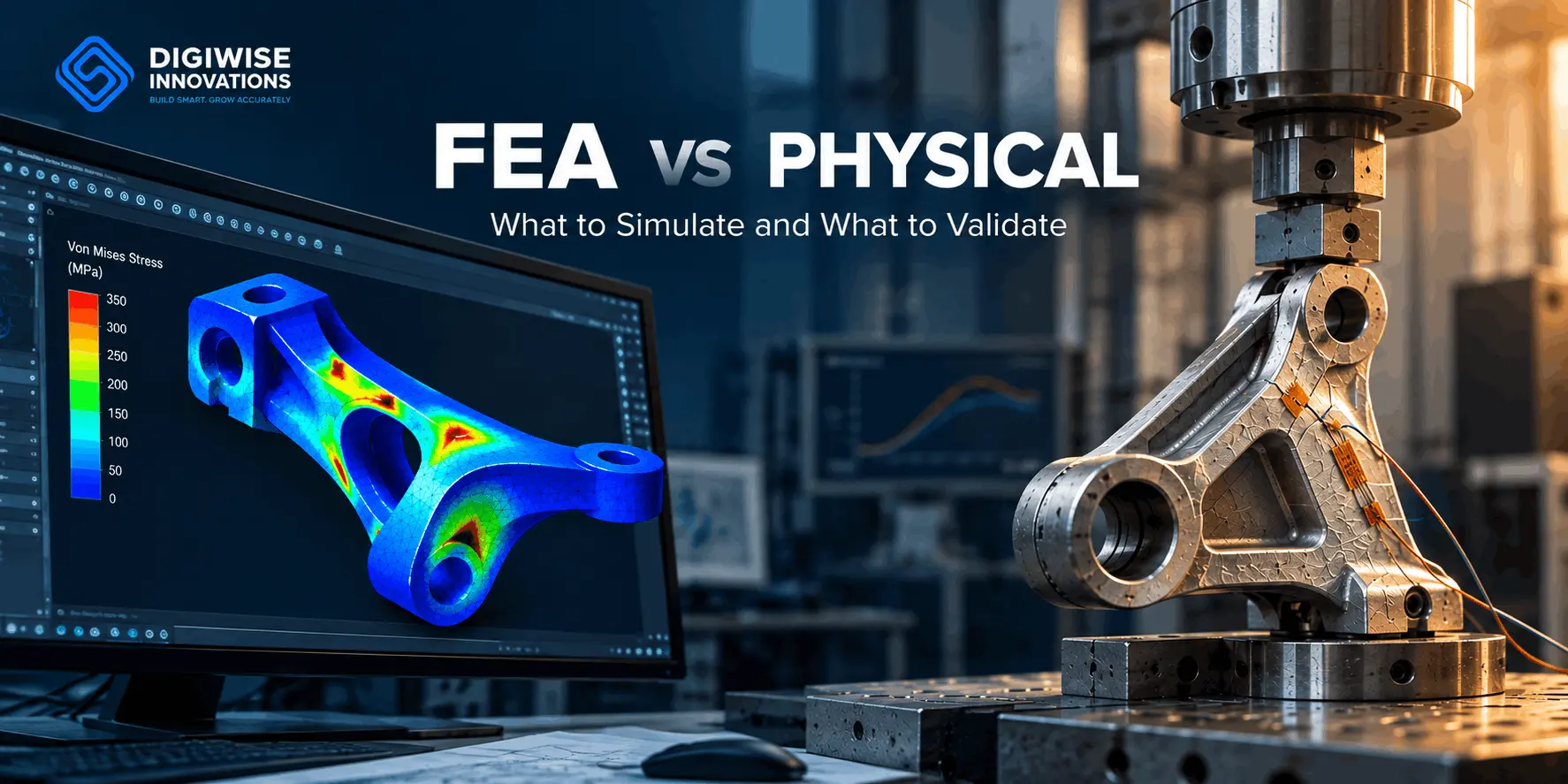
Before investing in a physical prototype, engineering teams need a practical way to judge whether a design can perform under its intended operating conditions. The useful question is rarely whether simulation or testing is better in the abstract. It is which evidence is needed for the decision at hand. FEA can help teams compare concepts, identify critical regions and investigate likely behaviour before manufacturing. Physical testing shows how a real specimen responds when it is loaded, heated, assembled or vibrated in a controlled setup. Confidence in either result depends on the quality of the inputs, the assumptions, the operating conditions and the purpose of the assessment. This guide explains FEA vs physical testing in practical terms: what to simulate before prototyping, when a test is necessary and how to evaluate predictions and measurements together.
FEA vs Physical Testing: Key Differences
FEA and physical testing address the same engineering problem from different directions. A simulation predicts how a simplified representation of the product should respond to defined inputs. A test measures how a physical specimen actually responds within a defined procedure. One is especially useful for exploring possibilities; the other provides evidence from the built configuration. The comparison below helps frame the choice without treating either method as a universal substitute for the other.
| Dimension | FEA | Physical testing |
| Primary purpose | Explore predicted behaviour and compare options before a product is built. | Observe the response of a physical specimen under defined conditions. |
| Inputs | Geometry, material models, loads, constraints, contacts and assumptions. | Specimens, instrumentation, fixtures, equipment and a controlled procedure. |
| Outputs | Predicted stresses, deformation, temperatures, modes or other calculated responses. | Measurements at instrumented locations, with a record of the actual test setup. |
| Design changes | Update geometry or assumptions and rerun the model. | Modify or manufacture a specimen, then repeat the test when needed. |
| Cost and time | Depend on model complexity, available data, analysis scope and review effort. | Depend on prototype cost, instrumentation, test setup, sample count and test duration. |
| Limitations | Sensitive to input quality, modelling choices and the conditions represented. | Affected by measurement uncertainty, fixture effects, specimen variation and limited coverage. |
The table is not a scorecard. Cost and lead time depend on model complexity, available data, prototype scope and the risk of the decision. The right approach is the one that provides enough evidence for the consequence of being wrong.
What Should You Simulate Before Building a Prototype
Simulation is most valuable when it is linked to a specific decision. Start by asking what uncertainty must be reduced before committing to a prototype, rather than modelling every CAD detail simply because it is available.
Compare Design Alternatives
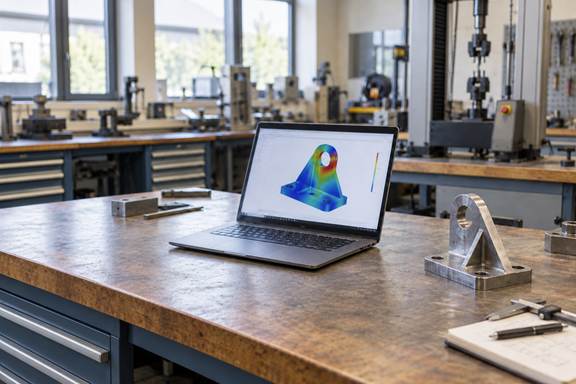
Model credible options when the team is choosing thicknesses, rib layouts, joint locations, materials or load paths. The purpose is to identify which options are more likely to meet the requirement and which carry clear risk. Apply the same meaningful load cases to each concept before prioritising the next iteration.
Comparing alternatives early can help teams reduce engineering risk before manufacturing and focus prototype testing on the most promising design.
Identify Critical Regions
FEA can reveal where stresses, deformation, contact pressure or temperature gradients are concentrated. These regions guide design changes and later testing. A mounting feature, fastener interface or thin transition may deserve closer inspection. The useful output is a decision about where to reinforce, measure or simplify, not just a coloured plot.
Assess the Behaviour That Drives the Decision
Choose analyses that reflect the mechanism that matters. For mechanical loading, structural FEA services help predict stress and displacement; temperature changes and their structural effects may require thermal and coupled-field analysis, while resonance concerns may need a modal study. Define the needed output in advance, such as displacement at an interface, strain at a critical location, temperature at a sensitive part or a natural frequency outside an operating range.
Unknown contact conditions, poorly characterised materials and uncertain load histories should be recorded as uncertainties, not hidden behind a more detailed mesh. The plan should identify the data that needs to be measured or confirmed later.
For structural problems, linear vs nonlinear FEA is another important choice: the model must represent any material, geometric or contact changes that influence the required output.
When Is Physical Testing Necessary
Physical testing is necessary when a decision needs evidence about real behaviour that the model cannot establish with enough confidence. Targeted tests can supply inputs, expose assumptions and validate a model early enough to improve the design.
Material Behaviour Is Uncertain or Critical
Published material properties are a useful starting point, but a manufactured part can differ because of grade, heat treatment, orientation, batch variation, temperature or manufacturing route. If the decision depends on yield, fatigue, stiffness, damping or thermal behaviour, coupon tests or supplier data may be needed to define a defensible model.
Assembly and Fixture Effects Matter
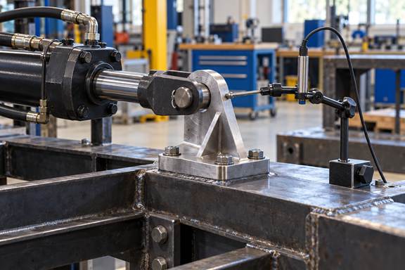
A component seldom works in isolation. Bolt preload, joint clearance, fixture stiffness and assembly sequence can alter its response. A model can represent these effects, but its assumptions must be supported. Testing an assembly or representative subassembly often shows whether real interfaces match the intended model.
Operating Conditions Are Not Well Defined
If load direction, duty cycle, environment or user interaction is uncertain, a test can reveal conditions not represented in the analysis. Instrumented trials may establish more realistic boundary conditions for the next simulation. Testing then reduces the uncertainty that limits the model.
External Requirements Demand Evidence
Applicable standards, customer specifications or internal release procedures may require physical test results, even when simulation informs the design. Identify the required evidence at the start so the analysis plan, prototype and test procedure support the same acceptance decision.
When yielding, large deformation or changing contact conditions influence the response, nonlinear FEA may be needed to represent the relevant behaviour.
How to Validate FEA Results Against Test Data
Validation asks whether a model represents physical behaviour well enough for its intended use. It is not a universal error percentage. Set acceptance criteria according to the decision, risk, expected uncertainty and applicable requirements. A model used to rank concepts needs different evidence from one supporting a safety-critical release.
Define Equivalent Quantities and Conditions
First, decide what will be compared: displacement at a point, strain near a feature, temperature at a sensor, force, pressure or natural frequency. Match geometry, loading, supports, contact conditions and measurement locations as closely as practical. A prediction at one point cannot be compared with a measurement made elsewhere under a different boundary condition. Document both setups.
Account for Uncertainty Before Judging a Difference
Include material variability, manufacturing tolerances, specimen geometry, fixture stiffness, sensor placement, calibration and measurement resolution. These factors can change the measured response even when the model is sound. Recording them gives the team a realistic basis for judging whether a discrepancy matters.
Verify the Numerics Separately
Mesh convergence, solver settings and numerical verification are essential, but they are not physical validation. A converged model can still use an unrealistic material law, load path or boundary condition. Check numerical behaviour first, then use experimental evidence to assess the real system.
Investigate Differences and Avoid False Validation
When results differ, inspect the assumptions before changing the model. Review the actual test load, supports, dimensions, interfaces and sensor locations. A discrepancy can reveal a modelling error, an unrepresented mechanism or a test setup effect. Calibration can improve a model’s fit to one test, but it is not independent validation. Where feasible, assess the revised model against a separate load case or specimen.
Example: Combining Simulation and Testing
Consider a metal mounting bracket that must support a defined static load without excessive deformation. The team has three candidate geometries and needs to choose one before investing in a prototype. A combined workflow could look like this:
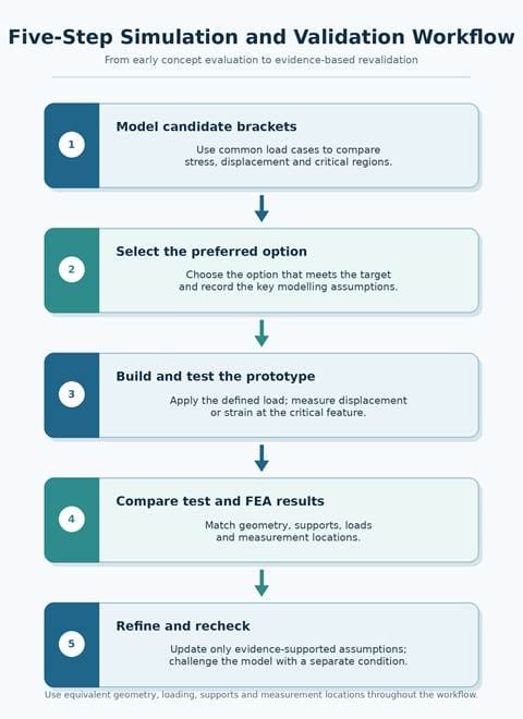
- Model the candidate brackets with the same mounting arrangement, material assumptions and applied load. Compare predicted displacement, stress distribution and the locations most likely to control the design.
- Select the option that best meets the intended performance target while retaining a clear record of assumptions that could influence the prediction, such as support stiffness and bolt behaviour.
- Manufacture the selected prototype and apply the defined load with a controlled fixture. Measure displacement at the relevant feature or strain at the critical region identified by the model.
- Compare the test results with the corresponding prediction under equivalent conditions. Do not compare a free-end displacement from the model with a measurement affected by an unrepresented fixture movement.
- Investigate any material discrepancy. Revise only assumptions that are supported by evidence, then, where practical, challenge the revised model with a separate load level or setup rather than relying on the same test used for calibration.
The example illustrates the different roles of the two methods. FEA reduces the number of alternatives that need to be built. Physical testing checks the selected configuration and strengthens the evidence for the decision. Neither step is complete without a clear definition of the operating condition it represents.
A Practical Simulation and Testing Checklist
Before launching an analysis or prototype test, align the team around a short set of questions. This makes the work traceable and prevents an impressive-looking result from answering the wrong question.
- What engineering decision must this work support, and what happens if the decision is wrong?
- Which outputs matter most: displacement, strain, temperature, natural frequency, fatigue life or another response?
- What geometry, material data, loads, contacts and boundary conditions are available, and which are uncertain?
- Which alternatives should be compared before a prototype is made?
- Which assumptions require a physical check because of manufacturing, assembly or operating variability?
- What test setup, fixture, instrumentation and measurement locations will match the model closely enough for comparison?
- What acceptance criteria are appropriate to this decision, and do standards or customer requirements prescribe any evidence?
- If the model is calibrated, which separate condition will be used to assess its predictive capability?
Frequently Asked Questions
Can FEA completely replace physical testing?
Not in every situation. FEA can reduce prototype iterations, compare alternatives and investigate behaviour that would be difficult to observe directly. Physical testing is still needed when real material or assembly behaviour is uncertain, when requirements demand measured evidence or when the intended use of the model requires validation against experimental data.
Why do FEA results differ from experimental results?
Differences can arise from material variation, geometry tolerances, fixture stiffness, contact conditions, load application, sensor placement or measurement uncertainty. They can also result from modelling assumptions that omit a relevant physical effect. The productive response is to compare equivalent conditions and investigate the source of the difference rather than assuming either result is automatically correct.
Should simulation or physical testing come first?
Often, simulation comes first because it helps teams focus prototype effort on the most promising configurations. Early tests may still be the first step when material behaviour, loading conditions or an assembly interface are unknown. In many projects, a small targeted test provides the inputs for FEA, and a later test checks the selected design.
How do engineers determine whether an FEA model is sufficiently validated?
They define the intended use, compare relevant predicted and measured quantities under matched conditions, account for uncertainty and judge the result against decision-specific criteria. Numerical checks such as mesh convergence support confidence, but they do not substitute for experimental validation. A calibrated model should ideally be assessed against separate evidence before it is relied upon for new conditions.
Conclusion
FEA and physical testing are complementary tools for making stronger engineering decisions. Simulation helps teams explore options before committing to hardware, while testing provides evidence of how a real product behaves and whether the model is fit for purpose. Start with the decision, define the outputs that matter, make uncertainties visible and connect the model to an intentional test plan. If your team is deciding what to simulate, what to test or how to validate a model against measured data, Digiwise can help define a practical analysis and verification approach for your product and operating conditions.