


Choosing between linear and nonlinear FEA is not a choice between a basic model and an advanced one. It is a decision about which physical effects must be represented to support the engineering decision at hand. Linear FEA assumes that the structure responds proportionally within a defined range: material stiffness remains effectively constant, deformation does not materially change the load path, and interfaces behave in a predictable way. Nonlinear FEA is needed when one or more of those assumptions no longer describes the relevant behaviour.
The practical objective is simple: use the simplest model that adequately represents the physics governing the decision. A well-scoped linear analysis can be the right tool for an elastic stiffness or stress check. A nonlinear model becomes necessary when yielding, large rotation, changing contact, instability or loading history can change the answer. More complexity does not compensate for missing loads, uncertain materials or poorly defined supports.
- Linear FEA is valuable when elastic behaviour, small deformation and stable interfaces are defensible assumptions.
- Material, geometric and contact effects are the three principal sources of structural nonlinearity.
- The same component may need a linear screening study for one question and a nonlinear assessment for another.
- A useful FEA brief defines the operating condition, required output and the inputs that remain uncertain.
Linear vs Nonlinear FEA at a Glance
Both methods can be credible when their assumptions fit the task. The difference is not that nonlinear FEA is automatically more accurate or more conservative. A nonlinear model can capture effects that a linear model cannot, but it also requires more data and more judgement. The table below frames the choice in practical terms.
| Dimension | Linear FEA | Nonlinear FEA |
| Structural assumptions | Elastic material response, small-enough deformation and stable, linearised interactions. | Includes relevant changes in material behaviour, geometry or contact state. |
| Load–response relationship | Response is proportional to applied load within the modelled range. | Response may be curved, path-dependent or affected by previous loading. |
| Stiffness | Usually constant throughout the analysis. | Can change as a part yields, bends, buckles, opens, closes or slides. |
| Material behaviour | Typically linear elastic. | May include plasticity, nonlinear elasticity, hyperelasticity, creep or other laws. |
| Contact and interfaces | Fixed, bonded, tied or appropriately linearised. | Surfaces may separate, engage, slide, stick or change pressure transfer. |
| Superposition | Valid when the assumptions remain linear. | Generally not valid; load sequence and preload can matter. |
| Solution approach | Usually a direct or iterative solve with one load state or simple load cases. | Uses load increments and equilibrium iterations; convergence must be assessed. |
| Modelling effort | Often faster to define, solve and compare for screening decisions. | Needs more complete inputs, careful controls and interpretation of the physical path. |
What Does Linear FEA Assume?
A linear structural model normally combines three assumptions. First, the material is represented as linear elastic, so stress and strain remain proportional and stiffness does not change over the relevant range. Second, deformation and rotation are small enough that the original geometry remains a reasonable basis for calculating equilibrium. Third, interactions such as supports, connections and contacts are either fixed, bonded, tied or approximated in a way that does not change during the load case.
When those assumptions are suitable, linear FEA has useful advantages. Doubling the load doubles the predicted displacement and stress, and separate load cases can often be combined through superposition. That makes it efficient for concept comparison, elastic stress checks, stiffness evaluation and many service-load calculations. The limitation is not that a linear solve is simple; it is that the result is only meaningful while the structure behaves in the manner the model assumes.
What Makes an FEA Model Nonlinear?
Nonlinearity enters a model when the relationship between load and response changes as the system deforms or is loaded. The source may be the material, the geometry, the interfaces between parts, or a combination of all three. Identifying the source matters because it determines which data, modelling controls and outputs deserve attention.
Material Nonlinearity
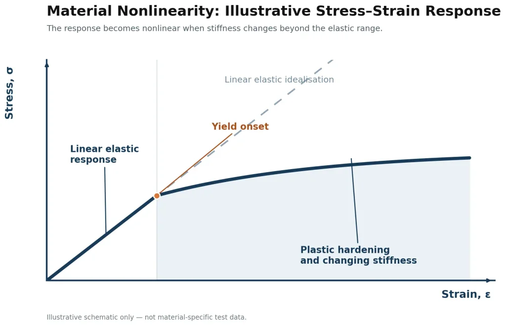
Material nonlinearity occurs when stiffness changes with stress, strain, time or temperature. Yielding and plastic deformation are common examples: after yield, a metal component can continue to carry load, but its incremental stiffness and permanent deformation differ from the elastic prediction. Rubber-like materials, foams, composites with nonlinear response and temperature-dependent metals may also need nonlinear constitutive data. The issue is not merely whether the model reaches a stated yield strength; it is whether the engineering decision depends on redistribution, residual deformation, local strain or energy absorption beyond the elastic range.
Geometric Nonlinearity
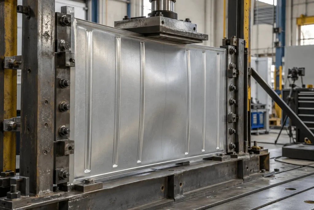
Geometric nonlinearity matters when deformation or rotation changes the load path, stiffness or equilibrium of the structure. A slender member that starts to bow, a bracket that rotates significantly, a cable that develops tension only after deflecting, or a panel approaching buckling can all behave differently from a small-displacement model. In these situations, the geometry seen by the load is not effectively fixed. Large deformation does not always mean failure, but it can invalidate a prediction that assumes the original shape continues to govern the response.
Contact Nonlinearity
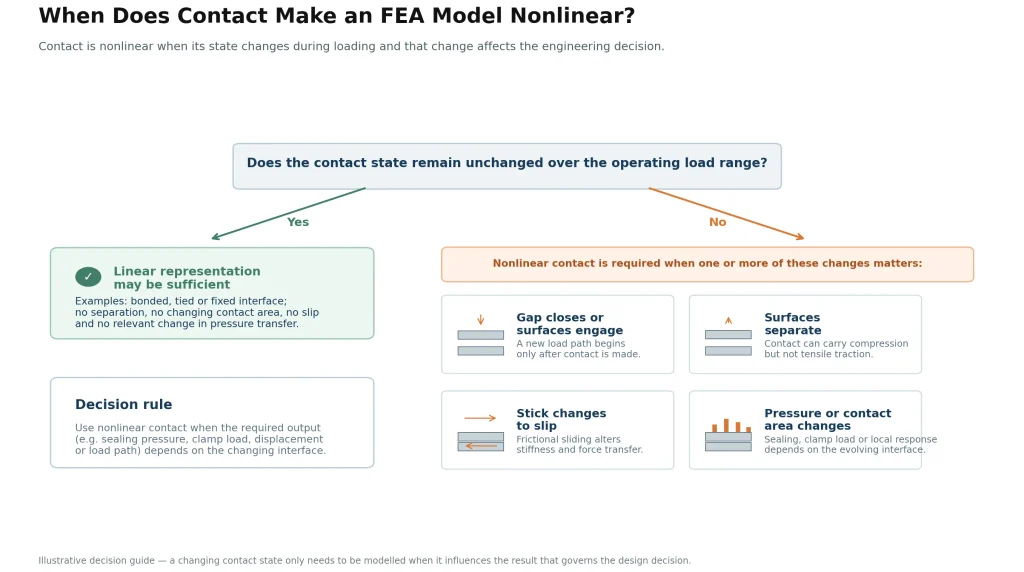
Contact nonlinearity arises when surfaces open, close, slide, stick or change pressure transfer. Bolted interfaces, latches, seals, bearings, stops, clips and assembled structures often include this behaviour. A support that can separate cannot pull the structure back; a joint that slips can lose stiffness; a gap that closes can create a new load path. Contact is therefore not automatically a reason to use a nonlinear model, but any change in contact state that affects the required output must be represented or supported by a defensible simplification.
When Is Linear FEA Sufficient?
Linear FEA is sufficient when the decision can be supported by an elastic, small-deformation representation of the relevant operating condition. Typical examples include comparing concept stiffness, checking an elastic stress level under a well-defined service load, estimating deflection of a rigidly connected frame, or identifying regions that deserve further attention. The key is that material response, geometry and interfaces remain close enough to the assumptions throughout the range being judged.
A linear model can also be an appropriate first step when uncertainty is high. It can screen several options using the same loads and supports, reveal likely critical regions and identify which data should be measured before a higher-fidelity assessment. It should not be presented as a final release analysis when the result is sensitive to yielding, instability, changing contact or a loading sequence that the model does not represent.
Early linear studies can help teams compare concept stiffness and screen design alternatives before committing to physical prototypes.
When Should You Use Nonlinear FEA?
Use nonlinear FEA when the relevant engineering output depends on a change that violates the linear assumptions. The following checklist is more useful than choosing an analysis method based on component size, solver capability or the desire for a detailed model:
- Will the material yield, harden, soften, recover nonlinearly or retain permanent deformation within the load range?
- Could deformation or rotation change stiffness, load direction, leverage, stability or the contact geometry?
- Do surfaces open, close, slip, stick, separate or transfer load only after a gap closes?
- Is buckling, snap-through, loss of support or another stability effect relevant to the decision?
- Does preload, assembly order, cyclic loading or an earlier load step change the condition for the next step?
- Are the required outputs plastic strain, residual set, contact pressure, clamp load, post-buckling response or another nonlinear quantity?
If the answer is yes to one of these questions, nonlinear modelling may be required. The next question is scope: which nonlinear effects actually influence the acceptance criterion? A model should include enough physics to make the decision defensible, not every possible feature of the real product.
Four Design Examples: Which Analysis Fits?
The examples below are illustrative rather than Digiwise project results. They show why the same part category can require different modelling choices depending on the operating condition and the output that matters.
1. Machined mounting bracket under a defined service load
A bracket remains well below yield, its bolted base is represented by a stable support condition, and the decision is whether elastic deflection and stress satisfy an internal limit. A linear model can be appropriate, especially for comparing several rib layouts or thicknesses. If the bracket may rotate enough to change the load direction, slip on its bolts, or yield locally around a lug, the final assessment may need geometric, contact or material nonlinearity.
2. Thin formed panel approaching instability
A thin panel may show low linear stresses while still being sensitive to local buckling or a stiffness drop caused by shape change. If the decision depends on the load after initial buckling, serviceability at a deflected condition or the effect of imperfections, geometric nonlinearity is more relevant than a simple elastic stress contour. A linear eigenvalue buckling study can provide a screening indicator, but it does not by itself represent the post-buckling load path.
3. Bolted cover with a compressed gasket
A cover may be stiff in isolation, yet sealing performance depends on how bolt preload, gasket compression and contact pressure are distributed around the interface. If the output is average structural deflection only, a simplified linear model may help early design. If the question is whether the seal remains compressed across a pressure cycle, the contact state and gasket behaviour can govern the answer and a nonlinear assembly model may be appropriate.
4. Mechanical stop or latch with local yielding
A stop can experience a brief impact-like engagement, local contact pressure and plastic deformation near the load path. A linear model may identify a likely critical region, but it cannot reliably predict permanent set, changing contact area or load redistribution after yielding. The final method depends on the actual loading rate and required output; nonlinear static, dynamic or explicit analysis are not interchangeable labels and should be selected to match the event.
How the Choice Affects Data, Effort, and Reliability
A nonlinear model usually requires more than a nonlinear solver setting. Material data may need a measured stress–strain curve, temperature dependence or a calibration basis. Contact requires realistic interfaces, friction assumptions, clearances and preload where relevant. Geometry may need imperfections, assembly positions or load steps that reflect the real sequence. The solution is commonly applied in increments, and a converged calculation should still be checked for sensible reactions, energy balance, contact status and response path.
Mesh sensitivity, solver convergence and validation answer different questions. Mesh sensitivity asks whether the numerical discretisation is adequate. Convergence asks whether the solver reached equilibrium for the specified model. Validation asks whether the model represents the physical system well enough for its intended use. None of these checks replaces the others. A reliable project plan identifies which uncertainty has the greatest effect on the decision and how it will be addressed.
What to Send an FEA Specialist
A concise project brief allows the analysis method to be scoped before modelling starts. Send what is known and label what is uncertain; unknown inputs are often the most important part of the discussion.
- CAD files, drawings, key dimensions and the configuration to be assessed.
- Material specification, available test data, manufacturing route and any temperature limits.
- Loads, load directions, load history, duty cycle and the operating condition to represent.
- Supports, fasteners, interfaces, clearances, preload and assembly sequence.
- Acceptance criteria and the outputs needed for the decision: stress, displacement, strain, contact pressure, permanent set or another measure.
- Available prototype measurements, previous failures, inspection data or known uncertainties.
Digiwise can help turn this information into a practical FEA scope, identify the inputs that most affect confidence and decide whether a linear screening analysis or a nonlinear assessment is appropriate. For fatigue, creep, fracture and remaining-life questions, explore our guide to nonlinear FEA for failure prediction and remaining life assessment so the analysis approach matches the specific failure mechanism.
Frequently Asked Questions
Is nonlinear FEA always more accurate than linear FEA?
No. It can represent relevant changes in material behaviour, geometry or contact, but only if the inputs and assumptions are credible. A nonlinear model with uncertain material data, unrealistic supports or an unrepresentative load path can be less useful than a well-scoped linear model. Accuracy depends on whether the model captures the physics that governs the decision.
Can a structure behave nonlinearly before the material yields?
Yes. Large rotation, buckling, gap closure, slipping interfaces and changing contact conditions can create nonlinear behaviour while the material remains elastic. Geometric and contact nonlinearity are independent of material plasticity.
Does contact always require nonlinear analysis?
Not always. A bonded or fixed interface may be represented linearly if that simplification is supported by the assembly and does not affect the required output. Nonlinear contact is needed when opening, closure, sliding, friction, separation or changing pressure transfer influences the decision.
Is nonlinear FEA the same as dynamic or explicit analysis?
No. Nonlinear describes the structural behaviour included in the model. Dynamic and explicit analyses describe different solution approaches or loading regimes. A static nonlinear analysis may be appropriate for slow loading, while a rapidly changing event may require a dynamic method. The physical event should determine the choice.
Can I start with a linear analysis and refine it later?
Often, yes. A linear screening model can compare options and identify critical regions efficiently. Refinement should be planned, however: document the assumptions, define the load range and decide which observations or calculations would trigger a nonlinear assessment. Do not treat the first linear result as final if its assumptions are already known to be outside the operating condition.
Conclusion
Linear vs nonlinear FEA is ultimately a question of relevance, not sophistication. Use a linear model when its elastic, small-deformation and stable-interface assumptions adequately support the decision. Use nonlinear FEA when material response, geometry, contact or load history changes the behaviour that matters. Share the geometry, operating loads, materials and acceptance question with Digiwise to define a practical, defensible analysis approach.