What We Develop
As part of our mechanical CAD design services, we develop:
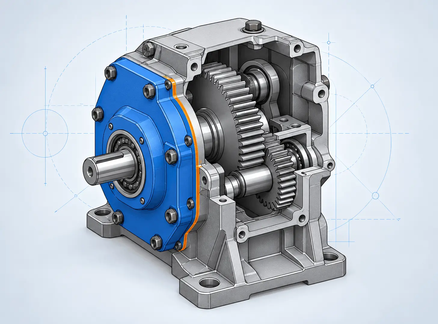
- Mechanical part models: define component geometry, key dimensions and features around the intended function.
- Assembly models: organize components and establish their positions, relationships and connection interfaces.
- Interface and clearance details: review mating features, mounting locations, gaps and potential interference.
- Design alternatives: compare configurations, component layouts and geometry changes before physical prototyping.
Modeling Matched to Your Design Requirements
Parametric Part Modeling
Develop mechanical components with features and dimensions that reflect how the design is intended to change. Depending on the part, this may include extrusions, revolutions, holes, patterns, fillets and other geometric features.
The model structure is selected to support meaningful revisions, such as changing a mounting pattern, wall thickness or overall envelope, without unnecessary dependencies.
Assembly Modeling
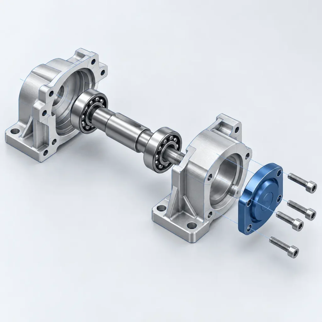
Build assemblies that represent how components fit together. Define component placement, mating relationships, fastening arrangements and relevant subassemblies.
The level of detail is matched to the project stage. An early layout may establish space and interfaces, while a detailed assembly may require defined mounting features, purchased components and assembly relationships.
Fit, Clearance and Interference Review
Review whether components occupy the intended positions without unintended overlap. Assess key gaps, fastener access, installation space and movement envelopes where these are relevant to the design.
Nominal CAD clearance does not establish fit across manufacturing variation. Tolerance analysis can be included separately when the decision depends on accumulated dimensional variation.
Design Iteration and Geometry Refinement
Update parts and assemblies as requirements develop or review findings identify improvements. Changes may address packaging, component access, assembly sequence, material selection or manufacturing constraints.
Where strength or stiffness influences the geometry, our structural and stress analysis services can support decisions about component dimensions and reinforcement.
Typical Applications
Equipment brackets and mounts, housings and enclosures, machine components, fixtures, mechanical supports and assembled products requiring defined component interfaces.
Projects may involve developing a new part, organizing an assembly layout or refining an existing design before prototyping.
Our Mechanical Design Process
- Define the function: establish what the component or assembly must do, its operating environment, available space and key interfaces.
- Review the inputs: assess sketches, drawings, existing geometry, materials, standard components and manufacturing constraints.
- Develop the models: build parts and assemblies with an appropriate feature structure, component relationships and level of detail.
- Review and refine: check geometry, fit, clearances and agreed functional requirements, then implement design revisions.
- Prepare the handover: deliver the agreed native models and exports, documenting assumptions and any requirements that remain unresolved.
What You Receive
Depending on the agreed scope, deliverables can include:
- Native CAD part and assembly files in the agreed software and version.
- Parametric features and assembly relationships suitable for the intended revisions.
- Neutral geometry exports, such as STEP or Parasolid, where supported.
- Defined component interfaces and key clearance information.
- Assembly views or exploded views for design communication.
- A component list or bill of materials when included in the scope.
- A summary of design assumptions, review findings and outstanding decisions.
Engineering drawings, detailed tolerancing, manufacturing documentation and simulation are agreed separately where required. A 3D model alone does not establish manufacturing readiness or validate physical performance.
What We Need to Get Started
Share your sketches, drawings, existing CAD files or product concept. Describe the intended function, overall dimensions, mating components and any space limitations.
Include preferred materials, manufacturing processes, standard components and relevant operating conditions where known. Let us know which CAD system and file formats you need, whether the model must remain parametric, and how it will be used after delivery.
If some requirements are still open, identify them at the start so we can distinguish confirmed inputs from assumptions that need further development.