What We Document
As part of our mechanical CAD design services, we prepare:
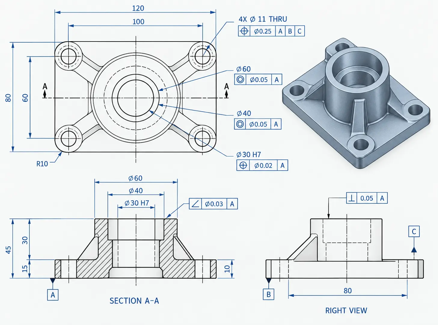
- Part drawings: communicate component geometry through appropriate views, dimensions and technical notes.
- Geometric tolerances: define allowable variation in form, orientation, location or runout where required by function.
- Assembly drawings: show component arrangements, item references and assembly information.
- Manufacturing details: document materials, surface texture, threads, treatments and other agreed production requirements.
Drawing Detail Matched to Your Requirements
Part Detailing
Create drawing views that communicate the geometry without unnecessary repetition. Sections, detail views and auxiliary views are included where standard projections do not adequately explain internal features or complex geometry.
Dimensions are arranged around functional features and the information needed to manufacture and inspect the component.
Dimensional Tolerances and Fits
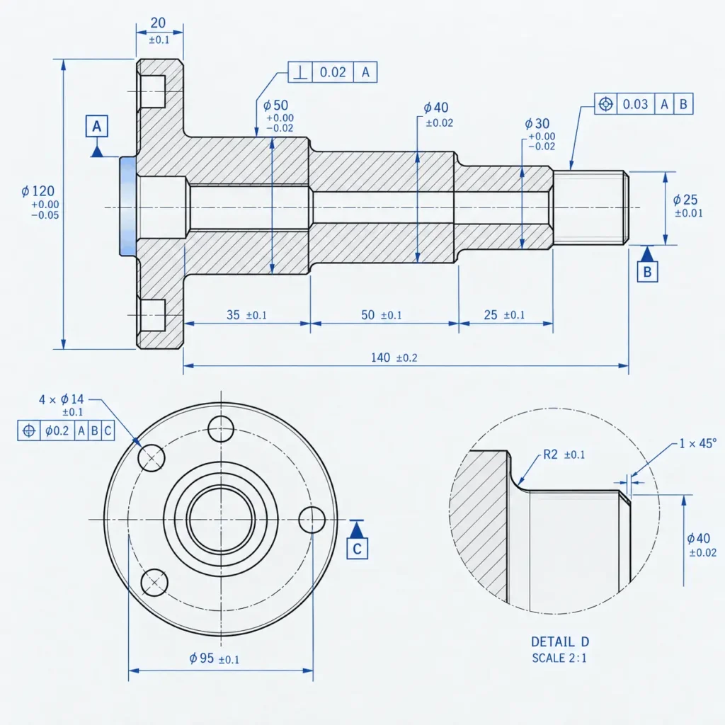
Define acceptable dimensional variation according to the component’s function and its relationship with mating parts. This can include hole and shaft fits, mounting dimensions, interface locations and clearance requirements.
Tighter tolerances are applied where justified. Unnecessarily restrictive requirements can increase manufacturing and inspection effort without improving product function.
Geometric Dimensioning and Tolerancing
Apply GD&T where size dimensions alone do not adequately control the required geometry. Depending on the feature, controls may address flatness, perpendicularity, position, profile or runout.
Datum features and reference systems are selected around how the component locates and functions in the assembly. The applicable ASME or ISO drawing and tolerancing framework is agreed at the start, with its conventions applied consistently.
Assembly Drawings and Technical Notes
Prepare assembly views with component identification, item balloons and a bill of materials where included. Add relevant installation or assembly requirements when these are defined by the design.
Technical notes can communicate material specifications, surface treatments, edge conditions and other requirements. Notes are reviewed alongside dimensions to avoid conflicting or duplicated instructions.
Where geometry or component relationships remain unresolved, our 3D mechanical design services can support part and assembly development before detailed drawings are finalized.
Typical Applications
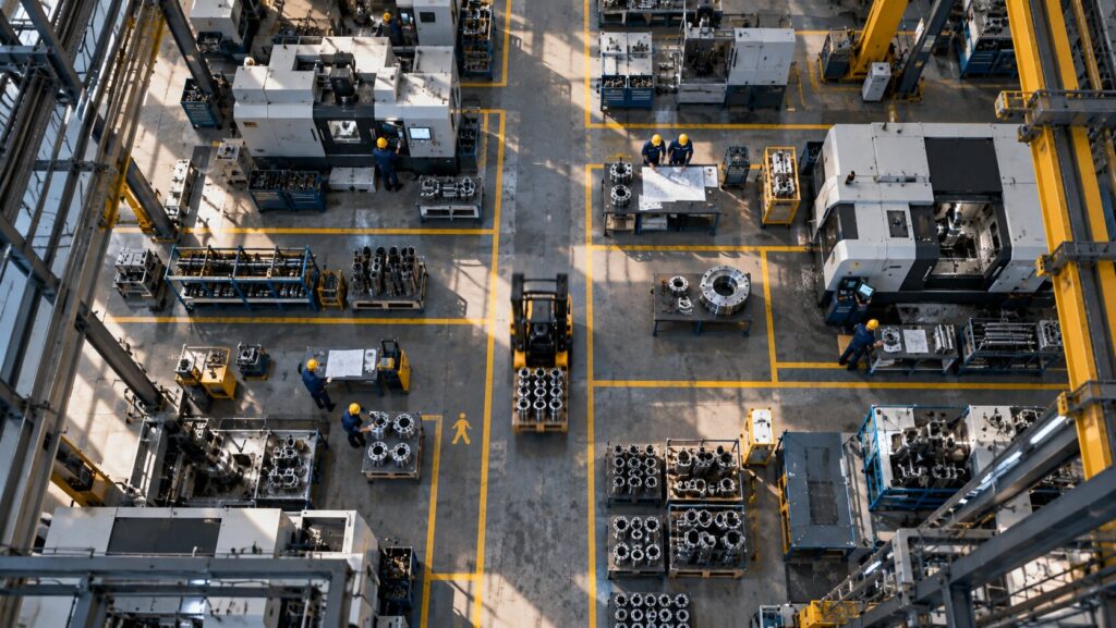
Machined components, mounting plates, brackets, housings, shafts, equipment parts and mechanical assemblies requiring documented manufacturing and inspection requirements.
Projects may involve detailing a new design, updating legacy drawings, revising supplier documentation or preparing a controlled drawing package for quotation and production planning.
Our Engineering Drawing Process
- Define the drawing purpose: establish whether the package supports quotation, prototyping, production, assembly or inspection.
- Review geometry and interfaces: assess source models, mating components, functional dimensions and unresolved design information.
- Develop the drawing package: prepare views, dimensions, tolerances, datum references and technical notes within the agreed framework.
- Review clarity and consistency: check drawing-to-model alignment, tolerance requirements, references and potentially ambiguous instructions.
- Issue the agreed deliverables: provide drawing files with revision identification and document any outstanding decisions.
What You Receive
Depending on the agreed scope, deliverables can include:
- Detailed part drawings with appropriate views and sections.
- Dimensions, dimensional tolerances and fit requirements.
- GD&T annotations and datum references where needed.
- Material, surface texture and treatment specifications.
- Assembly drawings with item references and a bill of materials.
- Native drawing files and PDF exports.
- DWG or DXF files where required and suitable for the intended use.
- Revision identification and a summary of unresolved requirements.
Tolerance stack-up calculations, inspection planning and changes to the underlying design are specified separately where required. A drawing package communicates agreed requirements; manufacturing capability and inspection arrangements should also be confirmed with the relevant suppliers.
What We Need to Get Started
Share your CAD models, existing drawings and any available assembly information. Identify critical interfaces, mating parts, required clearances and features that control function.
Include material specifications, intended manufacturing processes, surface requirements and known supplier constraints. Let us know your preferred drawing standard, units, templates, CAD system and file formats.
If tolerances or datum references have not been defined, explain how the part locates, connects and operates so these requirements can be developed around its intended use.