

A successful mechanical design must be producible, practical to assemble, and able to meet its functional, quality, strength, and service requirements. Manufacturability and assemblability should be reviewed before release for production.
Design for Manufacturing (DFM) focuses on producing parts reliably with a chosen process; Design for Assembly (DFA) focuses on how parts are positioned and connected. Design for Manufacturing and Assembly (DFMA) brings both perspectives together. [1, 3] Its aim is to balance production, assembly, performance, quality, and serviceability.
1. The Core Difference Between DFM and DFA
DFM asks, “Can this part be produced reliably with the selected process?” DFA asks, “Can the parts be assembled correctly, in a practical sequence, with adequate tool access?”
DFM considers material, geometry, tool access, tolerances, and inspection. A deep feature may require special tooling or extra CNC operations. DFA considers part count, fasteners, orientation, and assembly sequence. Self-locating features can aid positioning but must not compromise joint strength or disassembly. [2, 4]
| Criteria | DFM | DFA |
| Primary objective | Make parts manufacturable | Make assembly efficient |
| Typical review items | Material, geometry, process, inspection | Part count, joints, sequence, access |
| Typical output | Geometry or process changes | Joint or assembly-sequence changes |
| Key constraint | Preserve function and quality | Preserve strength and serviceability |
DFMA methods use different criteria and tools at different design stages; a systematic review found that one universal method for every product and phase remains challenging. [5]
2. Design Parts Around the Manufacturing Process (DFM)
Manufacturability depends on the process, so a geometry suited to CNC machining may not suit sheet-metal fabrication or casting. Consider the process early. [2, 6] For a sheet-metal belt-and-pulley guard, cut-outs, bend geometry, clearances, and forming sequence affect production. Multi-piece designs also require joining access and joint inspection.
Process, production volume, and supplier capability
Each process has constraints: sheet metal needs a workable flat pattern and bend sequence; machining depends on tool access and setups; molding requires geometry suited to the mold and release method. Changes must fit the actual process while preserving strength and quality.
Volume influences tooling. Flexible processes may suit small batches, while dedicated tooling may suit higher volumes. Consider complexity, setup effort, lead time, inspection, and unit cost. DFM still helps low-volume work because prototypes can be difficult to make. [1, 5]
Supplier capability matters: equipment and process-control differences may make a design straightforward for one fabricator but difficult for another. Review tooling and inspection capability with the supplier; process-specific checklists can help. [6]
3. Design the Assembly Sequence (DFA)
DFA considers parts as elements of a complete assembly. Components must be practical to position and connect. Separate parts need handling, orientation, and fastening; removing one can simplify assembly, but integration may make production or repair harder. [1, 4]
Check tool access and installation paths. A fastener may be clear in CAD but inaccessible to a wrench once assembled. Locating features improve positioning, and the installation sequence must be practical.
Serviceability and maintenance
Serviceability is how readily a product can be inspected, repaired, and maintained. Bolted joints may be easier to reopen than permanent joints, but numerous fasteners add work. A separate component may be preferable when it is likely to be damaged and can be replaced independently. Minimum part count is not the only measure of DFA success. [1, 4]
4. Example: Reviewing a Belt-and-Pulley Guard
Consider a hypothetical sheet-metal belt-and-pulley guard with a body, cover, mounting features, and fasteners. It protects moving components while allowing inspection and maintenance. Two options illustrate the DFM/DFA trade-off.
Option A: Separate mounting bases
Separate bases are attached to the guard body. For DFM, the body and bases may suit the supplier’s existing equipment, although the bases and joints add production and inspection work. For DFA, the extra parts require positioning and fastening. A damaged base may be replaceable independently, depending on joint design and access.
Option B: Integrated mounting features
The mounting features are formed into the guard body as tabs or flanges. DFA may improve because separate bases and fasteners are eliminated. DFM depends on whether the geometry suits cutting and forming; the flat pattern or bend sequence may need revision. An integrated feature may be harder to repair, and its strength must be checked for expected loads.
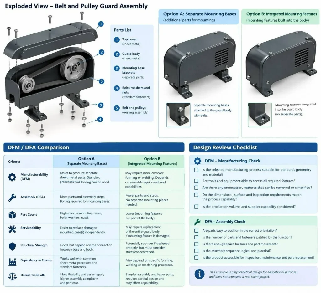
| Criterion | Option A: Separate bases | Option B: Integrated features |
| Manufacturability | Separate parts may suit available processes. | Depends on forming capability and geometry. |
| Assembly | Requires separate installation steps. | Eliminates separate base installation. |
| Part count | Higher. | Lower. |
| Serviceability | A base may be replaced independently. | Repair may involve more of the guard. |
| Strength | Verify the base-to-body joint. | Verify the formed feature and surrounding material. |
| Main trade-off | More parts, potentially easier repair. | Fewer parts; greater design dependence. |
Neither option is universally superior. The choice depends on process capability, volume, supplier equipment, loading, quality requirements, and maintenance needs. This is a hypothetical design example, not a client project.
5. Where DFM and DFA Can Conflict
A decision that simplifies manufacturing can complicate assembly or repair. Integrating parts may reduce joints but create a more complex component; splitting parts may simplify production while increasing assembly steps. Evaluate these trade-offs over the product’s expected life. [2, 5]
Set tolerances according to function, joint type, and process capability. Overly tight tolerances complicate production and inspection; inadequate ones can cause fit or performance problems. No single tolerance suits every component. Changes to sheet thickness or mounting geometry must reflect expected loads. Structural and stress analysis can support the review.
6. When to Review DFM and DFA
Review DFM and DFA at the concept stage, while part count, layout, and joints can still change. In detailed design, check geometry, tolerances, fastener locations, tool access, and assembly sequence. A CAD model without interference is not necessarily practical to assemble.
Before release, align drawings, materials, dimensions, tolerances, inspection requirements, and the bill of materials with the final design. Reassess if the supplier, volume, or process changes. A manufacturing drawing checklist can help ensure that the drawing package is complete.
7. CAD Deliverables That Support DFMA
A 3D CAD model shows geometry and assembly relationships, but production needs supporting documentation. Drawings define dimensions, tolerances, materials, and surface requirements. Assembly models and exploded views clarify connections and sequence; a bill of materials (BOM) lists components, and work instructions explain installation where needed.
For DFM, identify the process, critical features, and inspection requirements. For DFA, clarify joints, component locations, tool access, and assembly sequence. Where maintenance is expected, identify replaceable parts and explain disassembly. See mechanical CAD design services.
DFM / DFA review checklist
DFM — Manufacturing review
☐ Is the process suitable for the material and geometry?
☐ Can tools access all required features?
☐ Can nonessential features be simplified without harming function?
☐ Do tolerances and inspections match process capability?
☐ Have volume and supplier capability been considered?
DFA — Assembly review
☐ Can parts be positioned in the correct orientation?
☐ Are part and fastener counts justified by function?
☐ Is there enough space for tools and part movement?
☐ Is the assembly sequence practical?
☐ Can parts be inspected, repaired, or replaced?
This checklist is a starting point, not a substitute for a project-specific engineering review. The final assessment must reflect the actual process, requirements, and operating environment. [2, 6]
Frequently Asked Questions
What is the difference between DFM and DFA?
DFM focuses on producing parts reliably with the selected process; DFA focuses on assembling them correctly and efficiently. DFMA considers both. [1, 3]
Is DFMA suitable for low-volume production?
Yes. DFMA can identify issues in low-volume work. The solution depends on tooling, process, complexity, and supplier capability; improving geometry or assembly sequence may be more practical than dedicated tooling for a small batch. [1, 5]
Does reducing part count always improve a design?
No. Fewer parts can simplify assembly but make the remaining component harder to manufacture or repair. Consider function, strength, total cost, and serviceability. [2, 4]
Can a CAD model be manufacturable but difficult to assemble?
Yes. Parts may be individually manufacturable while the assembly lacks tool clearance, is difficult to position, or requires an impractical sequence. Manufacturability alone does not prove that an assembly can be built efficiently. [3, 4]
Conclusion
DFM focuses on manufacturability; DFA focuses on assembly sequence and efficiency. DFMA aligns both with process capability, production volume, supplier resources, and maintenance needs. The belt-and-pulley guard shows how separate or integrated mounting features affect production, assembly, strength, and repair. The best choice fits the project without sacrificing function or quality.
References
1. MIT Orbit Knowledge Base. “What Is Design for Manufacturing / Design for Assembly?” Open source
2. University of Florida. “Design for Manufacturing & Assembly (DFMA) Tips.” Open source
3. Autodesk. “What Is Design for Assembly?” Open source
4. Autodesk. “Design for Assembly Principles.” Open source
5. Formentini, G., Boix Rodríguez, N., & Favi, C. (2022). “Design for manufacturing and assembly methods in the product development process of mechanical products: a systematic literature review.” The International Journal of Advanced Manufacturing Technology, 120, 4307–4334. Open source
6. Boothroyd Dewhurst. “DFMA Guides & Downloads.” Open source