
Skip to content
Engineering Case Study

Flow-Induced Dynamic Stress Analysis for an Industrial Manifold

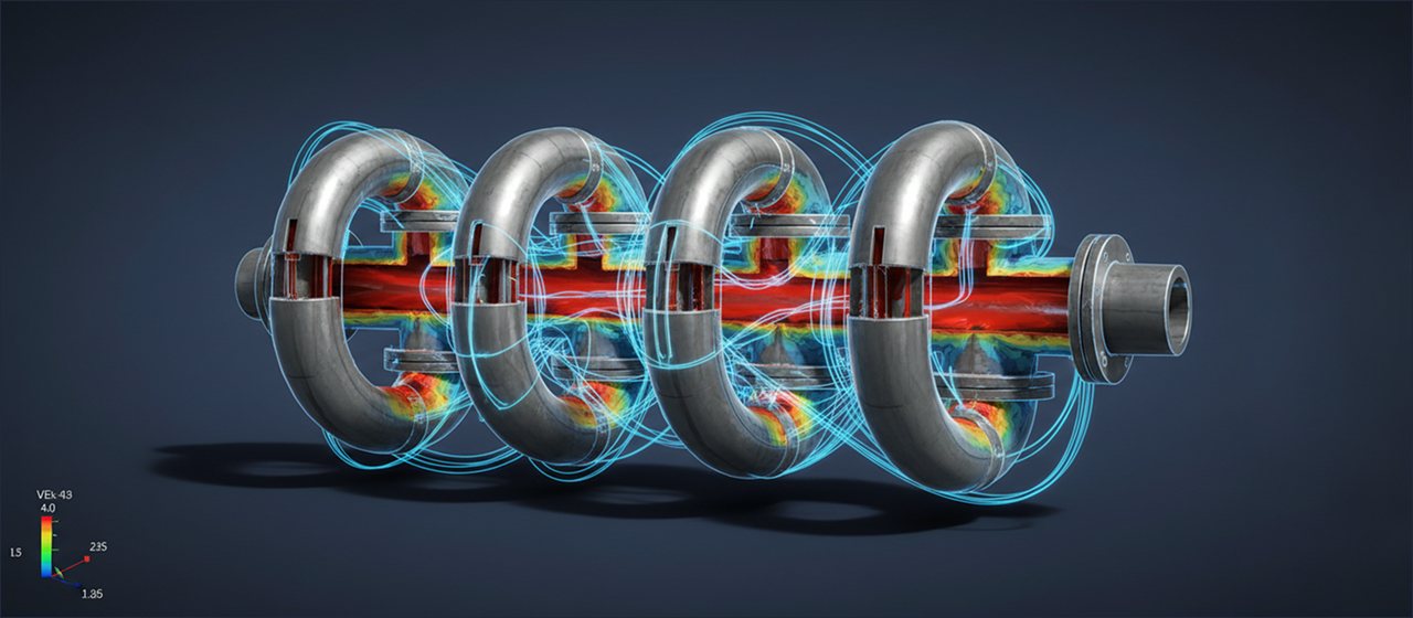
Predicting and mitigating vibration-induced fatigue in complex high-pressure manifold systems through advanced transient FSI (Fluid-Structure Interaction) modeling.

Flow-Induced Dynamic Stress Analysis for an Industrial Manifold
Client IndustryProcess & Petrochemical
Software UsedANSYS Fluent & Mechanical
Analysis TypeCoupled CFD-Structural (FSI)
Timeline Duration6 Weeks (Verification-Ready)
The Problem

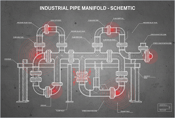
Vibration-Induced Fatigue at Piping Branch Junctions

A major chemical processor encountered premature mechanical failures at critical branch welds of their high-pressure fluid manifold. Pulsating flow caused by upstream pumps introduced complex, cyclic fluid-dynamic loads. This constant vibration risked catastrophic structural failure of the process line, threatening both production targets and facility safety.

Standard analytical ASME piping calculations were insufficient to capture the localized, multi-phase fluid physics and complex weld stress concentrations. The engineering team required a comprehensive transient numerical validation to evaluate fatigue life under actual pulsating operating conditions.

Vibration-Induced Fatigue at Piping Branch Junctions
Systematic Methodology

The Multi-Step Simulation Workflow

01

Fluid Domain CFD

High-fidelity transient CFD simulation in ANSYS Fluent to model pulsating pressure waves and turbulence structures.

02

Pressure Mapping

Time-varying pressure profiles mapped from the fluid boundary directly onto the structural FEA surface grid.

03

Structural FEA

Static and transient structural models run to calculate structural deformation, cyclic strain, and peak von Mises stresses.

04

Fatigue Estimation

Applying S-N curves and weld classification standards to predict dynamic fatigue life limits at hot-spot weld lines.

Overview

This section outlines the core assumptions, meshing strategy, and solver settings used to simulate flow-induced stress. The goal is to provide a clear, readable record of the methodology-making it easier to reproduce results and validate the model.

Meshing & Discretization

The mesh was generated using a hexahedral core strategy with localized refinement at weld fillets and interface junctions. This approach balances computational cost with boundary layer resolution, ensuring that the first-layer cell height is controlled to achieve a y+ value of ~1.

Key metrics

Total cell count: 12.4 million elements. The mesh is designed to support transient simulations with minimal numerical diffusion while maintaining a stable CFL condition.

Turbulence & Physics

The simulation employs the SST k-omega turbulence model with curvature correction. The PISO pressure-velocity coupling scheme is selected for stable transient formulation, and the time-step size is restricted to 1e-4 seconds to capture higher-order pressure harmonics.

Boundary conditions

Fixed piping support constraints are applied at anchor points matching physical structural hangers. A cyclic time-series pressure load is mapped dynamically using spatial interpolation to capture localized structural deflection.

Fatigue Evaluation

High-cycle fatigue evaluation is performed based on the ASME Boiler and Pressure Vessel Code Section VIII Div 2. Multi-axial fatigue is resolved using the Goodman relation and Rainflow cycle counting algorithms.

Post-processing

Results are extracted for key locations and summarized in a fatigue damage report. This includes stress cycles, usage factors, and critical locations identified by the solver.

Ready to Accelerate Your Engineering Innovation?

Partner with Digiwise Innovations for world-class simulation expertise and advanced computational engineering solutions.