

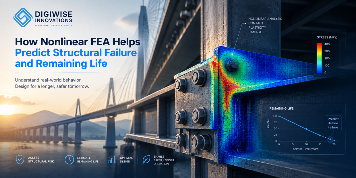
Structural failure rarely happens because of a single stress value. Real components may experience yielding, large deformation, repeated loading, creep, cracking, or changing contact conditions over time. Nonlinear Finite Element Analysis (FEA) helps engineers model these behaviors more realistically, identify how failure may develop, and support remaining life assessment before a component reaches a critical condition.
Key Takeaways
- Nonlinear FEA captures material, geometric, and contact nonlinearities that can control real structural failure.
- Failure prediction requires more than comparing von Mises stress with yield strength; damage, instability, cracks, cyclic loading, time, and temperature may all matter.
- Fatigue, creep, and fracture require different material data and different remaining-life assessment methods.
- FEA can connect operating loads to local stress and strain histories, damage accumulation, crack behavior, and ultimately remaining useful life.
- Reliable life prediction depends on realistic material models, loading histories, failure criteria, and validation.
What Is Nonlinear FEA?
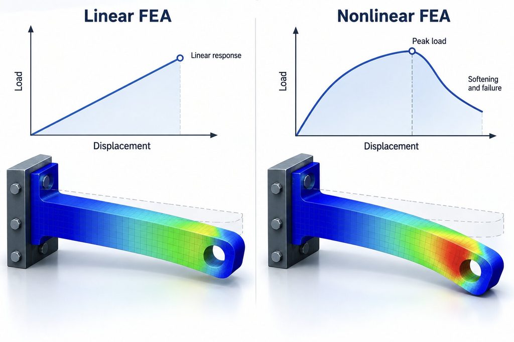
Nonlinear finite element analysis is used when a structure no longer responds proportionally to the applied load. This may happen because the material yields or damages, the geometry changes significantly, or contact conditions evolve during loading.
The three common sources are material nonlinearity, geometric nonlinearity, and contact nonlinearity. These effects are often central to structural failure because the behavior close to collapse can be very different from the initial elastic response.
Linear FEA is valuable for many design checks, but nonlinear FEA becomes important when engineers need to understand what happens after yielding, during large deformation, through changing contact, or as damage develops.
From Nonlinear Stress to Structural Failure
Structural failure is rarely defined by one stress contour alone. A component may first yield locally, accumulate plastic strain, initiate damage, develop a crack, and eventually lose its load-carrying capacity.
A nonlinear simulation can follow this progression and help answer practical questions: Where does failure initiate? At what load does permanent deformation begin? Does damage remain local or propagate through the structure? Which component fails first? What is the ultimate load capacity?
Elastic Response → Yielding → Plasticity → Damage Initiation → Damage Evolution → Structural Failure
Three Key Failure Mechanisms: Fatigue, Creep, and Fracture
Fatigue: Failure Under Repeated Loading
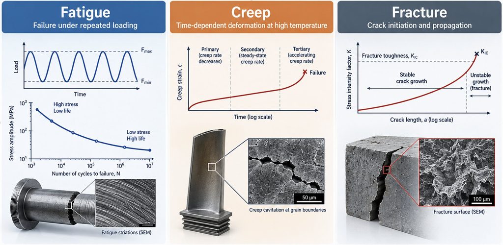
Fatigue occurs when repeated or fluctuating loads progressively damage a component. Failure can occur even when the peak stress is below the material’s static strength, making a simple one-time stress check insufficient.
FEA provides the local stress or strain histories needed for fatigue assessment. Depending on the application, engineers may use stress-life (S-N), strain-life (ε-N), or other fatigue approaches and account for cumulative damage from variable loading.
Typical examples include automotive suspension components under road loads, aircraft structures exposed to repeated flight cycles, rotating shafts and gears, and electronic solder joints subjected to thermal cycling. In each case, the important question is not only whether the component survives one load event, but how many cycles it can sustain.
Creep: Time-Dependent Failure at Elevated Temperature
Creep is time-dependent deformation that becomes important when a material operates for long periods under load, particularly at elevated temperature. A component may initially appear safe but gradually accumulate strain and damage over thousands of operating hours.
Creep analysis combines stress, temperature, time, and material creep data to predict deformation and support estimates of remaining service life. Depending on the problem, engineers may also need to consider stress relaxation and creep-fatigue interaction.
Applications include turbine and engine hot-section components, high-temperature piping, pressure equipment, and other energy or process-industry structures. Long-term thermo-mechanical loading can also be important in electronic packaging and polymeric materials.
Fracture: Crack Initiation and Propagation
Fracture analysis becomes critical when cracks, sharp defects, notches, interfaces, or pre-existing damage control structural integrity. A structure can have acceptable nominal stress while a local crack produces a much more severe failure risk.
Fracture-mechanics-based assessment uses crack geometry, loading, and material fracture properties to determine whether a crack is stable and how it may grow. Numerical techniques such as cohesive zone modeling (CZM) or XFEM can also be used for suitable crack and interface problems.
Examples include cracks in pipelines and pressure vessels, aerospace structures near highly loaded joints, weld-related defects, and delamination or interface failure in composite structures. Fracture assessment can therefore connect a detected defect to a decision about repair, inspection, or continued operation.
How FEA Supports Remaining Life Assessment
Remaining life assessment starts by identifying the mechanism that is actually consuming the component’s life. The same FEA result cannot be used in the same way for fatigue, creep, and fracture.
For fatigue, the target is commonly cycles to failure based on local cyclic stress or strain. For creep, the assessment is time-dependent and requires temperature, stress, exposure time, and creep properties. For fracture, the focus shifts to crack size, fracture resistance, and crack-growth behavior.
| Failure Mechanism | Key Inputs | Typical Life Assessment |
| Fatigue | Cyclic stress/strain and fatigue data | Cycles to failure |
| Creep | Stress, temperature, time, creep data | Time to damage or failure |
| Fracture | Crack size, loading, fracture properties | Critical crack or propagation life |
| Combined Damage | Loads, temperature, cycles, time | Creep-fatigue or mixed assessment |
Real components may experience interacting mechanisms. A high-temperature structure can accumulate both creep and fatigue damage, while a fatigue crack can eventually reach a size at which rapid fracture becomes possible. A credible remaining-life model therefore needs to reflect the dominant physics rather than applying one generic life formula.
Why Material Modeling Matters
Failure prediction is only as meaningful as the material model behind it. Elastic-plastic behavior may be sufficient for some collapse analyses, while other projects require cyclic plasticity, creep laws, ductile damage, composite damage, cohesive behavior, or specialized constitutive models.
When built-in material models are not sufficient, advanced FEA platforms such as Abaqus can be extended through user-defined routines such as UMAT or VUMAT. This is especially useful in research, new-material development, and specialized industrial applications where standard constitutive laws do not capture the measured behavior.
The objective is not to create a more complicated model for its own sake. The model should include the physical mechanisms that materially affect the engineering decision.
From Failure Prediction to Better Engineering Decisions
A useful failure analysis should lead to an action. Engineers may use nonlinear FEA and life assessment to change a geometry, reduce a stress concentration, select a different material, modify an operating limit, define an inspection interval, or determine whether a component can remain in service.
At DigiWise Innovations, structural analysis can combine nonlinear FEA, advanced material modeling, fatigue, creep, fracture mechanics, damage models, scripting, and user subroutines when required by the project. Tools such as Abaqus and ANSYS are selected around the physics and the engineering question rather than used as one-size-fits-all solutions.
Loads → Nonlinear FEA → Failure Mechanism → Damage / Crack Evolution → Remaining Life → Design or Maintenance Decision
Frequently Asked Questions
Can FEA Predict Exactly When a Structure Will Fail?
FEA can support failure and life prediction, but the accuracy depends on material data, loading history, model assumptions, failure criteria, and validation. Remaining-life results should therefore be treated as engineering estimates with clearly defined assumptions rather than exact universal predictions.
What Is the Difference Between Linear and Nonlinear FEA for Failure Analysis?
Linear FEA assumes a proportional response and is effective for many elastic design checks. Nonlinear FEA can represent yielding, large deformation, changing contact, damage, and other effects that become important as a structure approaches or progresses toward failure.
Can Nonlinear FEA Predict Fatigue Life?
FEA can calculate the local stress and strain histories used by fatigue-life methods. The subsequent life calculation requires suitable fatigue data and a method appropriate to the loading and material, such as stress-life or strain-life assessment.
What Data Are Needed for Remaining Life Assessment?
The required data depend on the failure mechanism. Fatigue needs cyclic loading and fatigue properties; creep needs stress-temperature-time data and creep behavior; fracture assessment requires crack information and fracture or crack-growth properties. Reliable operating history can be as important as the FEA model itself.
Predict Failure Before Failure Happens
Nonlinear FEA allows engineers to move beyond a simple pass-or-fail stress check and investigate how structures actually approach failure. By combining structural simulation with fatigue, creep, fracture, and appropriate material models, engineers can estimate damage progression and remaining useful life.
For product development and in-service structures alike, the value is practical: identify the critical mechanism, understand where and why failure may occur, and use that information to improve design, inspection, maintenance, or operating decisions.