
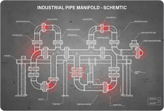
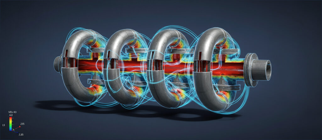
Flow-Induced Dynamic Stress Analysis for an Industrial Manifold
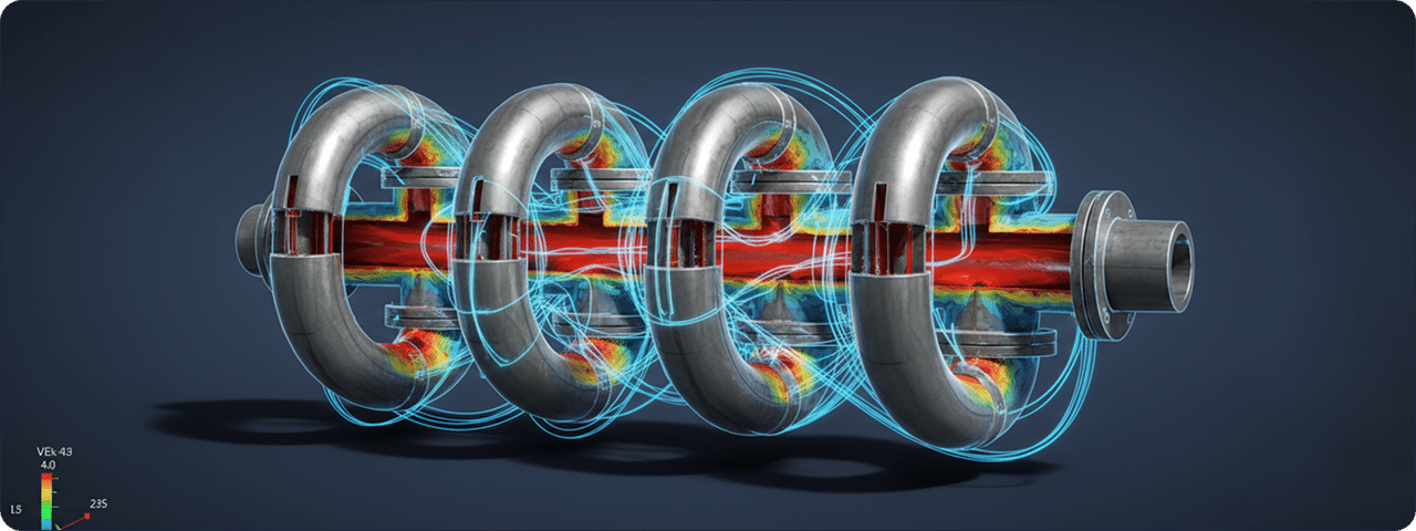
Predicting and mitigating vibration-induced fatigue in complex high-pressure manifold systems through advanced transient FSI (Fluid-Structure Interaction) modeling.
Read Case StudyExplore real engineering challenges, validated simulation workflows, and measurable results delivered across complex product-development programs.
Each case study documents the engineering question, modeling approach, validation process, and practical result so teams can see how simulation supports confident decisions.

Browse documented projects and discover how simulation-led engineering solved complex technical challenges.
1 items
Predicting and mitigating vibration-induced fatigue in complex high-pressure manifold systems through advanced transient FSI (Fluid-Structure Interaction) modeling.
Read Case StudyNo matching content was found. Try another search.

Our case studies provide a transparent view of how advanced simulation is applied to real engineering programs, from early investigation through final design validation.
Each project combines appropriate modeling fidelity with disciplined verification so results remain technically sound, repeatable, and useful to decision-makers.
The outcome is practical engineering insight that reduces uncertainty, focuses physical testing, and helps teams move forward with confidence.
Talk with our engineering team about your technical challenge and discover how simulation can support faster, more confident product decisions.
Native drawing files and PDF exports can be included in the deliverables. Assembly views, item balloons, bills of materials and additional export formats are provided when specified in the agreed scope.
Yes. The applicable drawing and tolerancing framework is agreed at the start, including relevant ASME Y14.5 or ISO GPS requirements where appropriate. We also review customer templates and project-specific documentation rules.
Dimensional tolerances define allowable variation in sizes or dimensions. GD&T controls geometric characteristics such as form, orientation, location and runout, using datum references where required. Both help communicate what variation is acceptable for the design.
Yes. We can prepare drawings from suitable CAD models, supported by information about materials, manufacturing processes, mating interfaces and functional requirements. Geometry alone does not define every tolerance or production requirement.
These can be included when specified in the project scope. Manufacturing drawings communicate production requirements, while simulation assesses performance under defined conditions. A 3D CAD model alone does not validate performance or establish manufacturing readiness.
Native, editable CAD files can be included in the agreed deliverables. The software, version and required parametric features are confirmed at the start. Neutral formats such as STEP can also be supplied, but generally do not preserve the original feature history.